pyRouterJig A woodworking layout tool for creating box and dovetail joints
Overview
When you start pyRouterJig, it will prompt you for the units you would
like to work in, as shown in the right window.
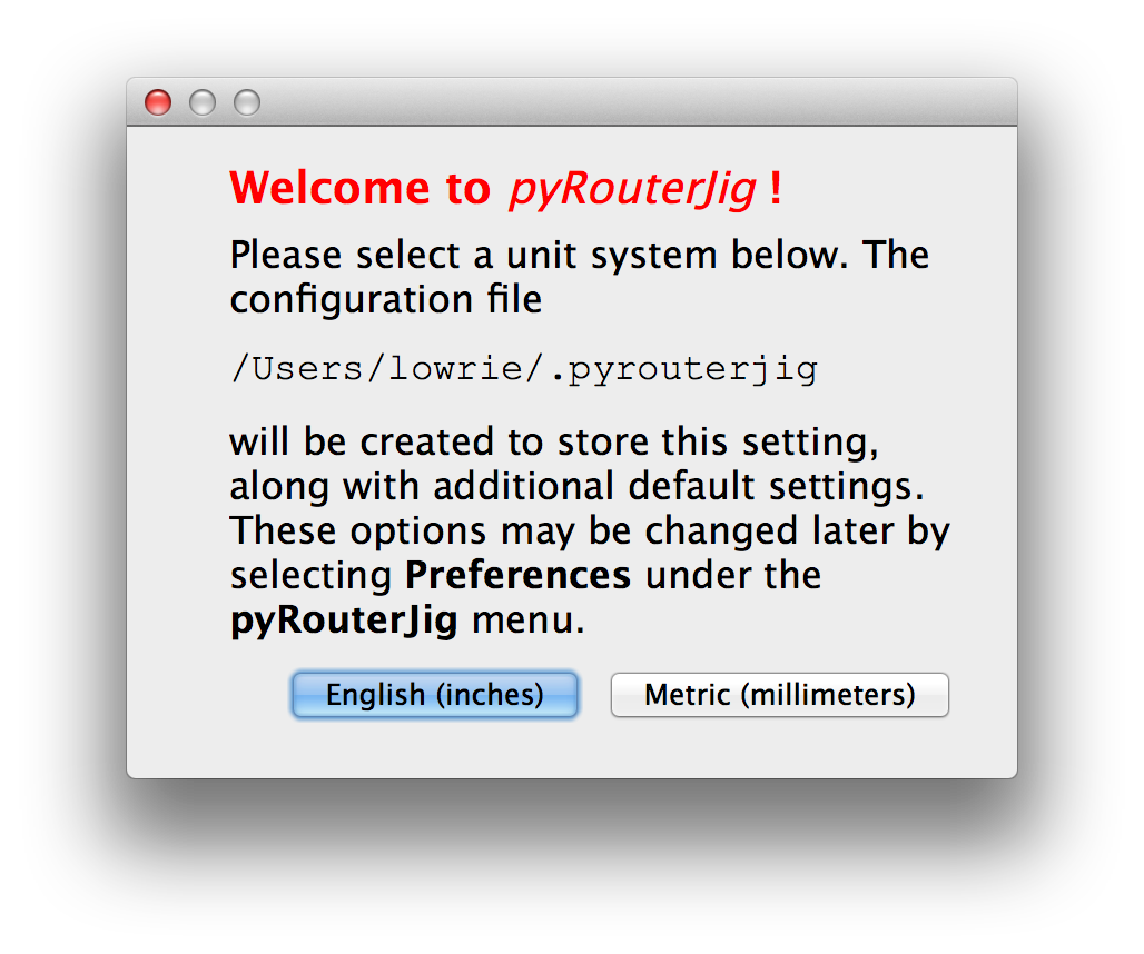 Your choice of unit system will be saved in a configuration file, which is
described in the section Saving Preferences, and you
will not be asked again.
Your choice of unit system will be saved in a configuration file, which is
described in the section Saving Preferences, and you
will not be asked again.
After selecting the units, a new window is created, and you should see something like the image below (this image is from a Windows platform; on other platforms, the image may differ):
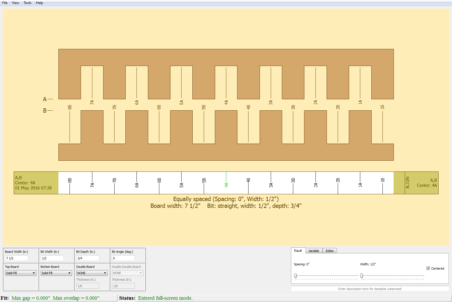
This documentation is focused on using English units, but any important differences will be discussed compared with metric units. The default joint is a box joint, with the fingers equally spaced, over a width of 7 1/2". The upper portion of the window draws the current joint.
Below the boards is the corresponding template that may be
cut out and used in an INCRA LS Positioner. See
Template Details
for more details on the templates. Below the template is a concise
title that summarizes the properties of the joint. The graphics containing the boards,
template, and title may be printed by selecting Print in the
File pull-down menu, or by pressing the key combination Ctrl-P
(Command-P on Mac).
The lower part of the window allows you to change interactively the parameters
for the joint. The joint is re-drawn after each change. In the lower-left grid,
 you can see two rows of input parameters, which are available for any
finger-pattern algorithm. On the top row, we have
you can see two rows of input parameters, which are available for any
finger-pattern algorithm. On the top row, we have
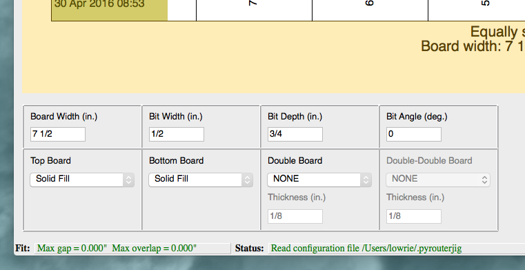
- Board Width [inches|mm]: The board width of the joint.
- Bit Width [inches|mm]: The maximum cutting width of the router bit.
- Bit Depth [inches|mm]: The cutting depth of the router bit.
- Bit Angle [degrees]: The angle of the router bit. Zero indicates a straight bit (box joint).
These parameters are changed by entering text for the dimension in their respective text boxes, shown in the image above. Moving the cursor outside the text box, or hitting the Enter key, will automatically update the value and redraw the joint with the new value. The values may be specified as either a fraction or decimal. For example, the following are equivalent:
7 1/2 or 7.5 or 7 1 / 2 or 7 1 /2 or 7 1/ 2
Note that the whitespace around the "/" is ignored. The board and bit
widths are rounded to the nearest alignment point. By default, alignment is
every 1/32" (or 1 mm for metric). See section Alignment of Router Passes for more
information about alignment.
On the bottom row of the lower-left grid parameters are Top Board, Bottom Board, Double Board, and Double-Double Board, which allow you to select the pattern or wood images used to draw these boards, along with parameters for Double and Double-Double joints. See the sections Wood Pattern Selection and Double Joints for more information.
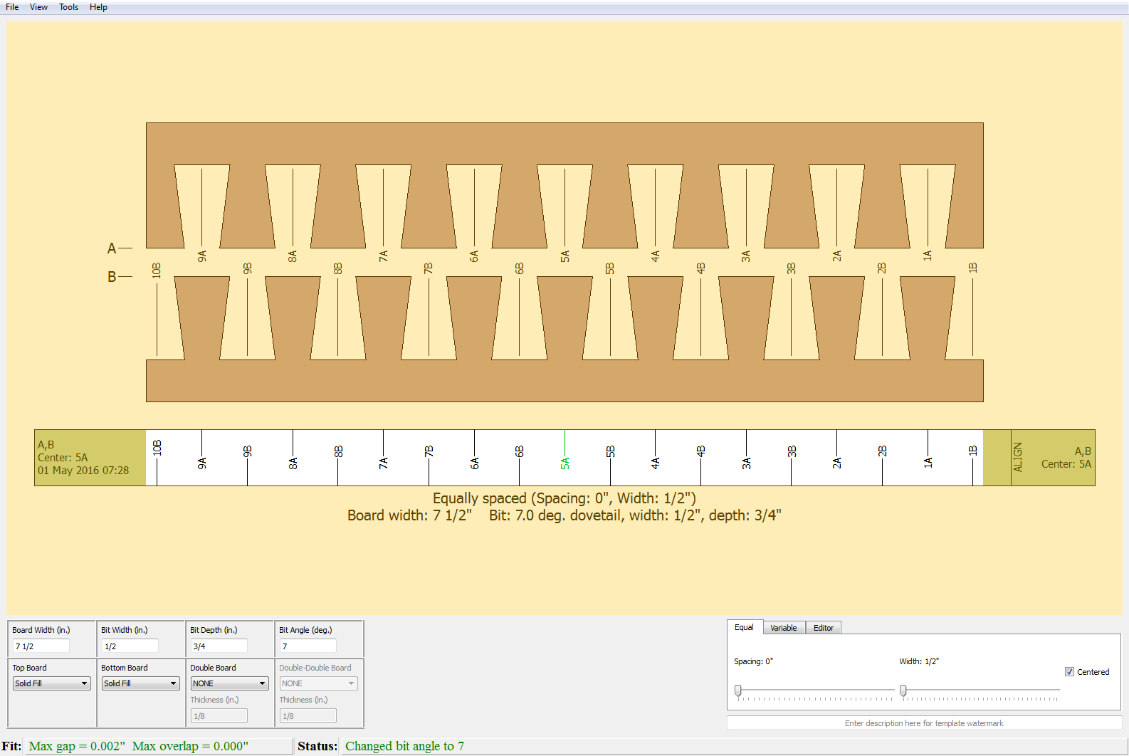
To create a dovetail joint, change Bit Angle to 7 degrees, and we obtain the dovetail joint shown in Figure 2 below:
On the bottom right of the window various finger layout options are available. See the section Finger Layout Options for information about Equal and Variable. The Editor always you to customize the finger patterns even further and is described in the section Editor. Below the finger layout options is the template watermark text box, which may be used to label the template.