pyRouterJig A woodworking layout tool for creating box and dovetail joints
Template Details
As mentioned above, the template may be cut out and used in a INCRA LS Positioner fence. Referring to any of the figures above, the template needs some explanation:
- The router passes are labeled with their ordering and the edge letter (A, B, C, etc.).
- The gray regions are margins for the template, outside the board's width. It's possible for a pass to be placed in the gray region, if the outer fingers are narrower than half of the Bit Width.
- A template may be aligned in one of two ways:
- Using the centerline of the template and the procedure explained in the
INCRA manual. For each template, either the centerline is shown as a dashed
line that spans the template height, or if the centerline coincides with a
cut, that cut denoted on each end of the template.
In this
example, the bottom template indicates that the centerline coincides with
cut
3E, whereas the top template draws the centerline between cuts5Cand6C.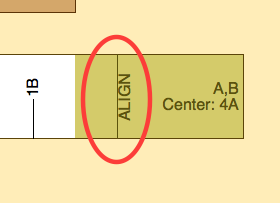
- The
ALIGNline is located 1/2 the bit width on the outside of the right edge of the board. Therefore, if you align your bit flush with the fence and then position the template at theALIGNline, your template will be properly positioned.
- Using the centerline of the template and the procedure explained in the
INCRA manual. For each template, either the centerline is shown as a dashed
line that spans the template height, or if the centerline coincides with a
cut, that cut denoted on each end of the template.
In this
example, the bottom template indicates that the centerline coincides with
cut
- On any one router pass, a good rule of thumb is not to cut deeper than the Bit Width. So for example, for a Bit Width of 1/2” and a Bit Depth of 3/4”, it’s best to run the board through twice, the first pass with the depth set at 3/8”, and the second pass at 3/4”. This rule of thumb may vary with the particular wood species, the sharpness of your bit, minimizing tear-out, and other variables.
- It's important that your printer not distort the template when
printing the template on paper. I have a cheap inkjet printer that
often distorts the template about 1/32” over 4”. This is well
outside the accuracy of an INCRA fence. If the print scaling appears
consistent across the page, you might try
changing the parameter
Print Scale Factorin the Preferences. But if all else fails, try the following steps:- Toggle the menu item View : Router Passes : Locations to turn on the location of each router pass. The locations are with respect to the right edge of the board.
- Align INCRA’s metal ruler with the board’s right edge. On the template, the right edge is located at the edge of the right, gray-shaded region. Ideally, you can locate the ruler so that its zero value is at the right edge, but this may push the ruler outside its channel. You really just need a reference value that you can easily add to the router pass locations displayed in Step 1.
- For each pass, the template will get you close. But you can also use the ruler to double check that the fence is at the precise location.